- 您现在的位置:买卖IC网 > Sheet目录1221 > IRADK10 (International Rectifier)KIT DESIGN 3-PH 115-230ACV MOTOR
�� �
�
�IRADK10�
�PWM� phase� command� signals�
�This� carries� the� signals� as� shown� below.� Note� that� these�
�signals� are� referenced� to� the� negative� DC� power� rail� which�
�is� not� at� ground� potential.� Beware� of� electric� shock� haz-�
�ard� and� do� not� connect� any� grounded� test� equipment�
�such� as� an� oscilloscope� to� these� test� pins.�
�Connecting� the� inverter� to� the� motor.�
�Use� a� 3-phase� 115V� Y� connected� or� 220V� delta� connected�
�induction� motor� rated� at� ?� HP� or� less.�
�Provide� a� 3� wire,� 2A� minimum� rated� cable� for� the� motor� con-�
�nection,� and� a� 3� wire� 2A� minimum� rated� cable� for� the� AC�
�mains� connections.� Make� sure� you� also� attach� the� ground�
�connection.� The� motor� phase� connections� can� be� connected�
�Pin� 1� :�
�Pin� 2� :�
�Pin� 3� :�
�Pin� 4� :�
�Pin� 5� :�
�Pin� 6� :�
�Pin� 7� :�
�Pin� 8� :�
�Pin� 9� :�
�Pin� 10� :�
�Pin� 11� :�
�Pin� 12� :�
�Phase� A� upper� switch� ON� command,� inverted�
�Phase� B� upper� switch� ON� command,� inverted�
�Phase� C� upper� switch� ON� command,� inverted�
�Phase� A� lower� switch� ON� command,� inverted�
�Phase� B� lower� switch� ON� command,� inverted�
�Phase� C� lower� switch� ON� command,� inverted�
�ITRIP� signal�
�SP1� spare� digital� input�
�SP2� spare� digital� input�
�GROUND� (0V)� referred� to� -� DC� bus�
�Spare� analog� input� referred� to� -DC� bus� rail�
�+5V� auxiliary� power� supply� referred� to� -� DC� bus�
�rail�
�in� any� sequence,� only� the� rotation� direction� will� be� affected.�
�Make� all� the� necessary� connections,� including� the� serial� link�
�with� the� PC� before� applying� AC� power.�
�Operating� the� motor� via� the� GUI� tool.�
�After� connecting� all� the� cables� and� selecting� the� desired�
�settings� in� the� GUI,� apply� the� AC� power� via� S2� in� position� 1.�
�After� a� few� seconds,� provided� the� main� voltage� is� within� tol-�
�erances,� the� yellow� LED� diode� will� flash� denoting� the� pres-�
�ence� of� the� DC-bus� voltage.�
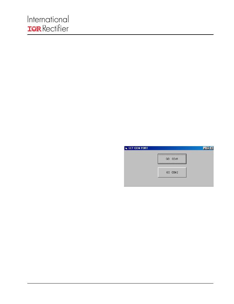
�Start� the� GUI� tool.� The� first� screen� will� prompt� you� for� the�
�COM� port� used� for� PC� to� DEMO� board� communication� as�
�High� voltage� signals� J2�
�is� showed� in� the� figure� 4.� Select� either� COM1� or� COM2� for�
�this� purpose.�
�This� connector� J2� carries� the� motor� drive� voltages� and� the�
�DC� bus� voltage.� Use� the� same� cautions� as� referenced�
�above� for� the� PWM� phase� command� signals.�
�Pin� 1� :� Phase� A� motor� voltage�
�Pin� 3� :� Phase� B� motor� voltage�
�Pin� 5� :� Phase� C� motor� voltage�
�Pin� 7� :� MINUS� DC� bus� rail�
�Pin� 10� :� PLUS� DC� bus� rail�
�Power� Connector� J1�
�Power� connector� provides� the� input� AC� power� and� the�
�motor� connections.�
�Pin� 1� :� Input� AC� voltage� (115V� or� 220V)� phase�
�Pin� 2� :� Input� AC� voltage� (115V� or� 220V)� neutral�
�Pin� 3� :� Ground� connection� (� has� to� be� connected� to�
�reduce� the� EMI� noise)�
�Pin� 4� :� Ground� connection�
�Pin� 5� :� Phase� C� motor� connection�
�Pin� 6� :� Phase� B� motor� connection�
�Pin� 7� :� Phase� A� motor� connection�
�110V/220V� selector� switch� S3�
�S3� is� the� selector� switch� to� set� the� correct� rectifier� configu-�
�ration� to� the� AC� input..� Prior� to� connecting� the� system� to� the�
�AC� input,� carefully� check� the� position� of� S3.� Operate� the�
�switch� only� when� the� AC� is� OFF� .� The� drive� will� be� dam-�
�aged� and� the� user� could� be� injured� by� ignoring� this� warning.�
�www.irf.com�
�Figure� 4.� GUI� serial� connection� selections�
�This� will� lead� you� to� the� next� screen.� Observe� at� the� top-left�
�a� white� field� with� the� “DRIVE� STATUS”� label.� Pressing� the�
�“REFRESH� SCREEN”� button� will� read� the� drive� status� (ON,�
�OFF,� eventual� SC,� OV,� UV,� I2T,� and� heat� sink� over� tempera-�
�ture)� and� print� a� message� in� the� top-left� white� field.� Below�
�the� “DRIVE� STATUS”� field,� another� white� field� is� observed�
�with� the� caption� “DC-link� current� average� value� over� 5� sec-�
�onds”.� Pressing� the� “REFRESH� SCREEN”� button� will� read�
�the� drive� DC-link� current� averaged� over� 5� seconds� and� dis-�
�play� the� value� in� mA� units.� Further� below,� in� the� same� far� left�
�column,� another� white� field� is� observed� with� the� caption� “Heat�
�sink� temperature”.� Pressing� the� “REFRESH� SCREEN”� but-�
�ton� will� read� the� drive� heat� sink� temperature� and� display� the�
�value� in� degrees� Centigrade.�
�5�
�发布紧急采购,3分钟左右您将得到回复。
相关PDF资料
IRADK31
DESIGN KIT 1/4 HP DC FOR IR31XX
IRAUDAMP1
KIT REFERENCE DESIGN W/IR2011S
IRAUDAMP4
KIT 2CH 120W HALF BRDG AUDIO AMP
IRCS2277S
DEMO FOR 3-PHASE/380V MOTOR DRV
IRDC2085S-DF
BOARD EVAL CONV DC BUS W/IRF6603
IRDC3038
KIT W/IRU3038 PWM CTRL DDR 14-PI
IRDC3039
BOARD EVAL CTRLR PWM W/IRU3039
IRDC3046
KIT W/IRU3046 DUAL PWM LDO CTRLR
相关代理商/技术参数
IRADK31
功能描述:电源管理IC开发工具 1/4 HP DC brushless Mtr using IR31xx
RoHS:否 制造商:Maxim Integrated 产品:Evaluation Kits 类型:Battery Management 工具用于评估:MAX17710GB 输入电压: 输出电压:1.8 V
IRADK-S10UP60
制造商:International Rectifier 功能描述:
IRAE410
制造商:MURATA 制造商全称:Murata Manufacturing Co., Ltd. 功能描述:PYROELECTRIC INFRARED SENSORS IRA SERIES
IRA-E410
制造商:MURATA 制造商全称:Murata Manufacturing Co., Ltd. 功能描述:PYROELECTRIC INFRARED SENSORS IRA SERIES
IRA-E410QW1
制造商:Murata Manufacturing Co Ltd 功能描述:PYROELECTRIC INFRARED SENSOR - Bulk
IRA-E410S1
制造商:MURATA 制造商全称:Murata Manufacturing Co., Ltd. 功能描述:PYROELECTRIC INFRARED SENSORS IRA SERIES
IRA-E410ST1
制造商:MURATA 制造商全称:Murata Manufacturing Co., Ltd. 功能描述:PYROELECTRIC INFRARED SENSORS IRA SERIES
IRA-E420
制造商:MURATA 制造商全称:Murata Manufacturing Co., Ltd. 功能描述:Dual Type Pyroelectric Infrared Sensor